
Lamnaflo Construction
| 01 | Stainless Steel Shrouds and Thread Adapters |
| 02 | Certa-Lok Coupling Connections
|
| 03 | Schedule 40 PVC Construction |
| 04 | Engineered Slot Patterns
|
| 05 | Wire Reinforced Epoxy Coated Silica Sand
|
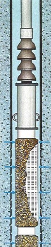
Engineered Placement
- Elements distributed through water Bearing Zone
- Even Distribution of Flow to Achieve a Laminar State
- Elements Placed to Promote Flow from Given Formation
- Flow Control Discs Inhibit Vertical Flow in Annular Space
- Promote Higher Water Quality
Dissipation of Suction Energy
| REF | ELEMENT | FUNCTION |
|---|---|---|
| 01 | Suction Flow Control Elements |
|
| 02 | Engineered Placement |
|
| 03 | EPiC Design |
|
Engineering Specifications
The well shall be equipped with a Lamnaflo Suction Flow Control System designed and manufactured according to US Patent Number 4,624,319 and 6,843,316 or other patents and patents pending by Lamnaflo, Inc., P.O. Box 306, Oconomowoc, WI 53066 (262) 269-6196.
Such system shall consist of an engineered assembly of reinforced permeable bodies constructed of an inert silica/epoxy compound matrix and high impact high tensile PVC pipe. The unit shall be engineered, designed, manufactured and assembled in a manner sufficient to precisely distribute pump suction energy over the screen or formation so as to eliminate areas of high-water velocity and sand production, as well as to maximize the water quality.
Each section of the system shall be connected to the next with a non-threaded flex coupling to allow for deviation in the well, as well as to prevent cross threading and over-tightening during assembly. Manufacturer of the system to be supplied shall demonstrate by means of verifiable independent references that others have successfully used systems supplied by them in similar applications for several years.
SEC. 02 — SPECIFICATIONS
Engineering Specifications
Requires no modification to your existing well. Adapts to either turbine or submersible pumps.